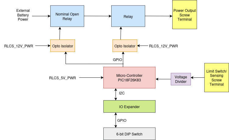
RLCS V4 Relay Board

Requirements (RelayBoard)
Req. ID |
Description |
Justification/Parent Requirement |
|---|---|---|
MECH. 1 |
Board shall be no larger than ? |
Proper mounting in EGSE respin |
MECH. 2 |
Board shall have M3 mounting hole on each of the corner |
For attaching to DIN rail mounting part |
ELEC. 1 |
Board shall have a screw terminal takes Battery Power, accept 12-16 awg wire |
For power input |
ELEC. 2 |
Board shall have a screw terminal takes 12V and 5V RLCS power, 18-22 awg |
12V powers relay coil and 5V powers MCU |
ELEC. 3 |
All power rail shall be proper decoupled |
General electrical design rule |
ELEC. 4 |
Board shall have DNP Keystone 5000 series testpoint on all on-board digital communication lines |
For debug with a logic analyzer later |
ELEC. 5 |
Board shall have one CAN connection, CAN connection shall have two screw terminal with pinout(CANH/CANL/GND), accept 22 awg ferrules, CAN connection shall have DNP termination resistor |
two screw terminal for daisy chain |
ELEC. 6 |
Board shall have 0805 LED for each power rail as ON signal |
for power diagnostics |
ELEC. 7 |
Board shall have 12-16 awg screw terminal for power output and limit switch input |
Connect to actuator/ignition or tank heater |
ELEC. 8 |
Board shall have voltage sense on Battery in, each power output line |
? |
ELEC. 9 |
Board shall have current sense on RLCS 12V and 5V in, Battery in, each power output line |
? |
ELEC. 10 |
All ADC input shall be low pass filtered with cutoff(-3dB) frequency of 20kHz |
? |