RLCS V4 Ground Launch Sequencer Board
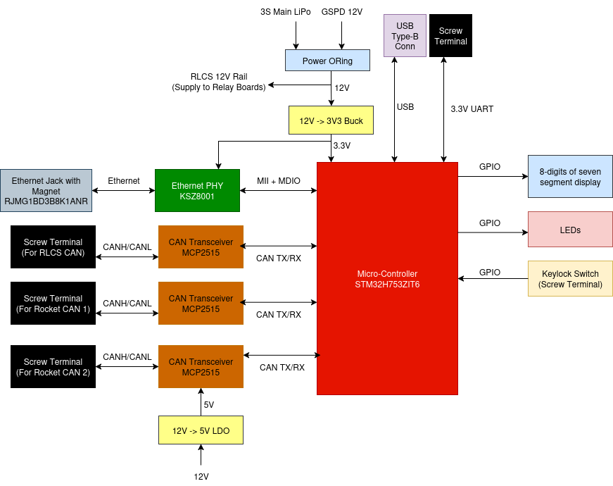
Ground Launch Sequencer board is the main controller board of RLCS Towerside. It act as a bridge between Ethernet interface and various CAN interfaces.
Requirements (GLSBoard)
Req. ID |
Description |
Justification/Parent Requirement |
|---|---|---|
MECH. 1 |
Board shall be no larger than 10 cm x 10 cm |
Proper mounting in EGSE respin |
MECH. 2 |
Board shall have M3 mounting hole on each of the corner |
For attaching to DIN rail mounting part |
ELEC. 1 |
Board shall have a screw terminal takes 12V LiPo Power, accept 22 to 18 awg ferrules |
The 12V LiPo is used as backup power |
ELEC. 2 |
Board shall have a screw terminal takes 12V GSPD Power, accept 22 to 18 awg ferrules |
Main power source |
ELEC. 3 |
Board shall have a simple power oring circuit between LiPo and GSPD 12V (TODISCUSS USB Power) |
Seamless switching |
ELEC. 4 |
Board shall have a 5-12V to 3.3V buck converter |
STM32 and KSZ8001(Ethernet PHY) needs it |
ELEC. 5 |
All IC shall be proper decoupled |
General electrical design rule |
ELEC. 6 |
Board shall have DNP Keystone 5000 series testpoint on all on-board digital communication lines |
For debug with a logic analyzer later |
ELEC. 7 |
Board shall have a Ethernet connection, provided with a MagJack(Ethernet Jack with built-in magnet/transformer) |
Reduce passive circuit on board |
ELEC. 8 |
Board shall have a three CAN connection, each CAN connection shall have a screw terminal with pinout(CANH/CANL/GND), accept 22 awg ferrules, Each CAN connection shall have a DNP 0805 SMD termination resistor |
? |
ELEC. 9 |
Board shall have a USB Type-B connection |
For dumping data over USB ACM device for CAN debugging |
ELEC. 10 |
Board shall have a 3.3V LVCMOS UART connection, on 22 awg screw terminal |
Backup if ethernet doesn’t work |
ELEC. 11 |
Board shall have a 3.3V power output screw terminal(May be shared with UART connection ELEC.10) |
To power UART-Ethernet converter if the board’s built-in ethernet Does not work |
ELEC. 11 |
Board shall have a total of 8 digits of seven segment display, shall be bright enough to view in daylight, should be made of 2x4 digit or 4x2 digit |
Display valve states |
ELEC. 12 |
Board shall have 0805 LED to display clientside arm state, towerside arm state, communication status, if system in safe state |
? |
ELEC. 13 |
Board shall have 0805 LED for each power rail as ON signal |
for power diagnostics |
ELEC. 14 |
Board shall have 18-22 awg screw terminal for 12V output(after power oring) |
For provide RLCS_12V to relay boards |
ELEC. 15 |
Board shall have 22 awg screw terminal for keylock switch |
? |
ELEC. 16 |
Board shall have voltage sense on GSPD 12V in, LiPo 12V in, USB 5V in |
? |
ELEC. 17 |
Board shall have current sense on GSPD 12V in, LiPo 12V in, USB 5V in, RLCS 12V out, RLCS 3.3V out |
? |