RLCS V4 Clientside Board
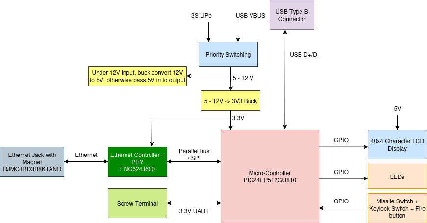
RLCS V4 Clientside board is the SRAD PCB inside the Clientside. The board connects to all internal electrical components in clientside. The board has a 5-12V to 3.3V buck converter to provide power to MCU, Ethernet Controller+PHY IC and missile switches. A 5-12V to 5V buck converter/switching circuit for providing power to LCD display. Ethernet Controller+PHY IC and Ethernet Jack with built-in magnet for Ethernet connection. A UART screw terminal as a back up solution of Ethernet does not work at board bring-up.
Requirements (ClientsideBoard)
Req. ID |
Description |
Justification/Parent Requirement |
|---|---|---|
MECH. 1 |
Board shall have M3 mounting holes |
Mount to RLCS Clientside face plate |
MECH. 2 |
Board should be stacked vertically with LCD Display, with matching mounting hole with LCD display, and matching vertical electrical connector |
Vertical connector can be used to ensure stable connection |
ELEC. 1 (TODO) |
Board should have power priority switching between LiPo 12V and USB VBUS(5V) |
Usually USB is connected to a computer with “unlimited” power source, so it should be priority |
ELEC. 2 |
Board shall have a 10/100 Mbps Ethernet connection(refer to diagram above) |
For communicate with towerside GLS board through local network |
ELEC. 3 |
Board shall have 3.3V LVCMOS UART connection |
Backup if ethernet doesn’t work |
ELEC. 4 |
Board shall have a 3.3V output screw terminal(should be on same screw terminal as UART) |
To power UART-Ethernet converter if the board’s built-in ethernet Does not work |
ELEC. 5 |
Board shall have DNP Keystone 5000 series testpoint on all on-board digital communication lines |
For debug with a logic analyzer later |
ELEC. 6 |
Board shall have a Type-B USB Connector, USB shall have ESD protection |
The board can be used for data logging |
ELEC. 7 |
Board shall have a screw terminal for connecting to missile switches(refer to Clientside MECH.3 requirement), fire button and keylock switch |
? |
ELEC. 8 |
Board shall have a screw terminal to supply missile switch LED power, need to able to supply 300mA |
TODO: calc |
ELEC. 9 |
Board shall have SMD 0805 LED for each voltage power rail and 5 LED connect to MCU GPIO for debugging purpose |
. |
ELEC. 10 |
TODO LED on panel |
. |
ELEC. 11 |
If required the LCD interface circuit shall have proper level shifting |
. |
ELEC. 12 |
There shall be voltage sensing on VBUS and LiPo power input |
. |
ELEC. 13 |
There shall be current sense on VBUS and LiPo power input, 3.3V power output and power output to LCD display |
. |
ELEC. 14 |
There shall be a screw terminal connect to a potentiometer for controlling LCD brightness/contrast |
. |